I was tasked with developing a comprehensive testing solution for printed circuit board assemblies (PCBA) that are returned from the field for reuse. The objective was to create a robust and efficient tester capable of thoroughly assessing the functionality and integrity of these cards before they are put back into service.
The tester definition and hardware design were completed by me, while the assembly was carried out by a Chinese contractor.

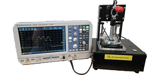
This tester ensures that each PCBA meets the required specifications and performs reliably by simulating real-world conditions, identifying any potential defects in order to check IR LEDs and reed switch , and confirming that all critical components function properly. By implementing this solution, we can effectively extend the life cycle of returned PCBAs, reduce waste, and improve cost-efficiency in the process.

The tester is designed to measure the illuminance from three separate LED units. It receives input from a light sensor that captures the wavelength of the LEDs’ light. This allows for precise monitoring of the light output and ensures that each LED operates within the desired specifications.

For the reed switch test, I utilized a magnetic solenoid that, when activated by the press of a button, generates a magnetic field. This magnetizes the reed switch, causing it to close the circuit and illuminate an indicator light, thereby confirming whether the circuit is closed or open.

What is Reed Switch?
A reed switch is a type of electrical switch that is activated by a magnetic field. It consists of two thin, ferrous (magnetic) contacts enclosed in a small glass tube. When a magnetic field is brought near the reed switch, the magnetic force causes the contacts to either attract and close (in the case of a normally open reed switch) or repel and open (in the case of a normally closed reed switch).