
The ATtiny85 Digispark USB is a small, programmable microcontroller board based on the ATtiny85 chip. It’s notable for its compact size and USB connectivity, making it suitable for various embedded projects where space and simplicity are key.
Schematic

PCB Layout

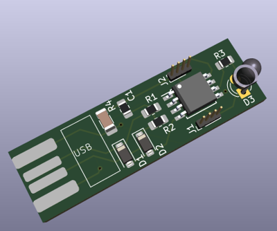
3D Model
What are the special considerations in planning a ATtiny85 Digispark USB circuit?
- Power Supply: The ATtiny85 typically operates at 5V, but the Digispark USB variant often includes a built-in voltage regulator to allow it to be powered directly from a USB port, which supplies 5V. Ensure that your power supply can provide stable power within the required voltage range.
- USB Interface: The Digispark USB has a built-in USB interface, allowing it to be programmed and communicate with a host computer via USB. Ensure that you properly connect the USB data lines (D+ and D-) and include any necessary components like pull-up resistors for USB enumeration.
- Bootloader: The Digispark USB bootloader allows for easy programming of the ATtiny85 via USB. Ensure that you allocate enough flash memory for the bootloader and leave adequate space for your application code.
- Clock Source: The ATtiny85 can operate using an internal oscillator or an external clock source. Choose the appropriate clock source for your application and configure it accordingly.
- I/O Pins: The ATtiny85 has a limited number of I/O pins (usually 6 usable pins in total). Plan your circuit layout carefully to ensure that you have enough pins for your application’s requirements.
- Peripheral Devices: If your application requires peripheral devices such as sensors, LEDs, or displays, ensure that you properly interface them with the ATtiny85 and allocate the necessary pins.
- Power Consumption: The ATtiny85 is known for its low power consumption, making it suitable for battery-operated applications. Optimize your code and circuit design to minimize power consumption where possible.
- Programming: Ensure that you have a suitable programmer or bootloader to program the ATtiny85, whether it’s the Digispark USB bootloader or an external programmer.
- Protection Circuitry: Consider including protection circuitry such as voltage regulators, reverse polarity protection, and overcurrent protection to safeguard your circuit and the ATtiny85 from damage.
- Testing and Debugging: Plan for ways to test and debug your circuit, such as using serial communication for debugging output or incorporating test points for measuring voltages and signals.
By considering these factors during the planning stage, you can design a robust and functional circuit.
With an ATtiny85 Digispark USB, you can create a wide range of projects, including:
- LED blinkers and light displays
- Sensors and data logging devices
- USB peripherals like keyboards or mice emulators
- Remote control devices
- Audio players or synthesizers
- Home automation and IoT devices
- Wearable technology such as smart jewelry or clothing
- Educational projects for learning about microcontrollers and electronics.
Here’s a simple code example using the Arduino IDE to program the ATtiny85 Digispark USB for LED blinkers and light displays:
// Pin definitions
#define LED_PIN 1 // Pin 1 is connected to the LED
void setup() {
pinMode(LED_PIN, OUTPUT); // Set LED_PIN as an output
}
void loop() {
// Blink the LED
digitalWrite(LED_PIN, HIGH); // Turn the LED on
delay(500); // Wait for 500 milliseconds
digitalWrite(LED_PIN, LOW); // Turn the LED off
delay(500); // Wait for 500 milliseconds
}