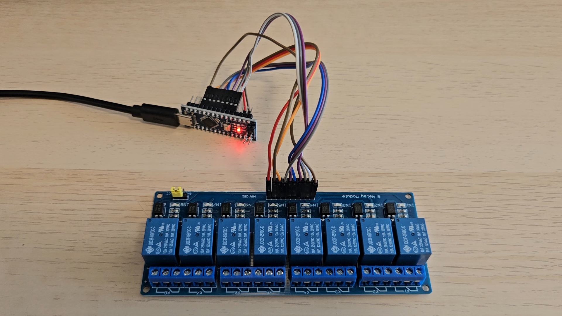
In this guide, I’ll walk you through controlling an 8-channel relay using an Arduino Nano. This setup is great for automating multiple devices or systems, such as home automation, robotics, or industrial applications where switching multiple components is essential.
What You’ll Need:
- Arduino Nano
- 8-channel relay module
- Jumper wires
- Power supply for the relay module (if needed)
- Components to control (e.g., LEDs, motors, lamps)
Wiring the Setup:
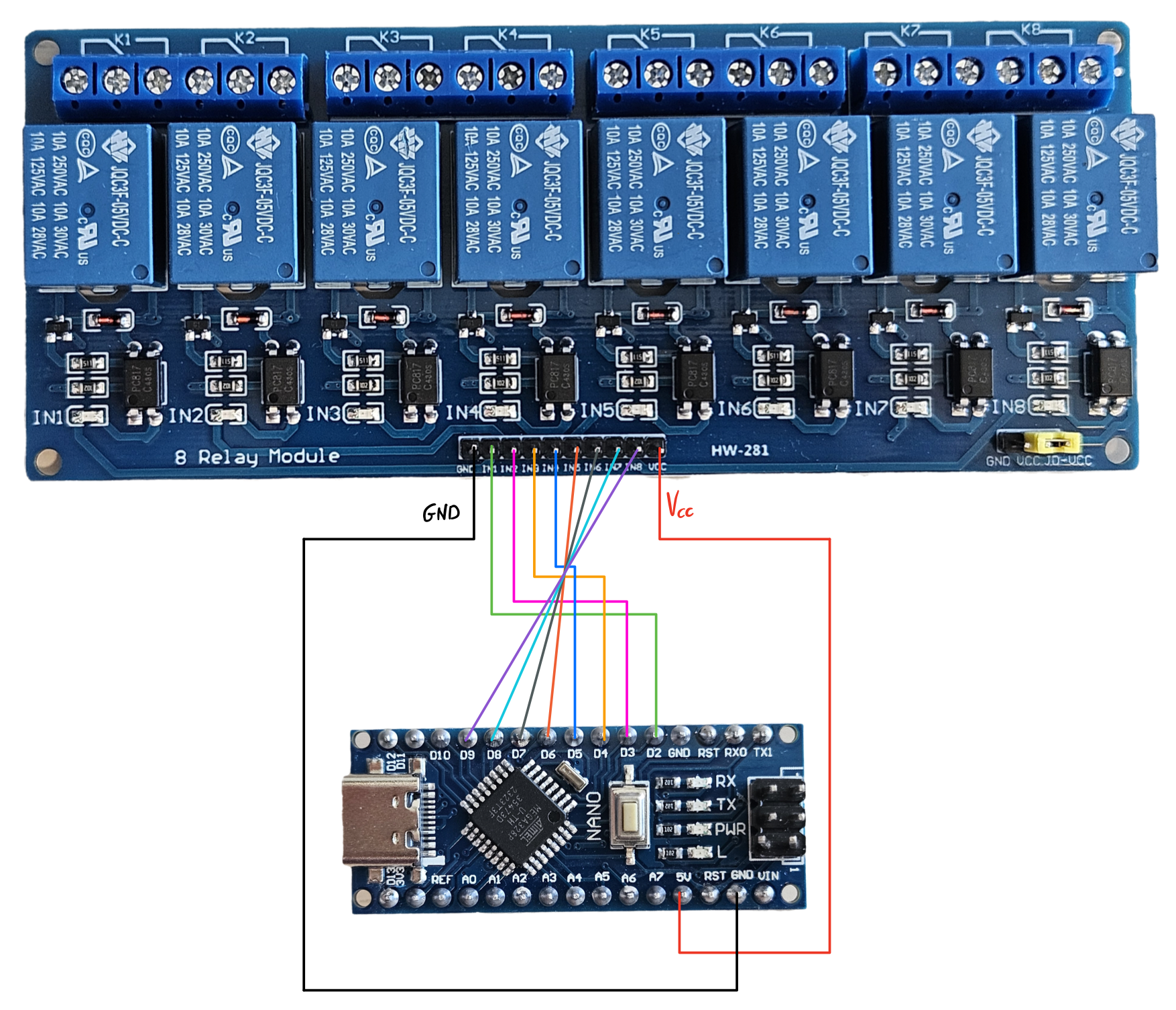
- Connect the Relays: Each relay will require a digital pin from the Arduino to switch it on or off. For this project, we’ll use pins D2 to D9. These pins will control the individual relays.
- Power the Relay Module: If your relay module requires external power, connect the VCC and GND pins to a 5V power supply. Otherwise, you can power it directly from the Arduino.
- Connect the Common Ground: Make sure to connect the GND of the Arduino Nano to the ground of the relay module to ensure a common reference for switching signals.
Note:
For more than 2 relays, connect an external 5V supply to Vcc and GND.
Why Use an External 5V Supply?
- The Arduino’s 5V pin can only supply a limited amount of current (usually around 500mA when powered via USB).
- Each relay typically draws around 70-100mA, so powering more than two relays directly from the Arduino could result in power issues.
- Using an external power source ensures reliable switching, especially in setups with multiple relays.
Scheme
The Code
Here’s a basic sketch to control the relays sequentially:
void setup(){ pinMode(2,OUTPUT);//D2 pinMode(3,OUTPUT);//D3 pinMode(4,OUTPUT);//D4 pinMode(5,OUTPUT);//D5 pinMode(6,OUTPUT);//D6 pinMode(7,OUTPUT);//D7 pinMode(8,OUTPUT);//D8 pinMode(9,OUTPUT);//D9}void loop() { digitalWrite(2,LOW);//IN1 set low delay(500);//IN1 set low duratino digitalWrite(2,HIGH);//IN1 set high delay(500);//IN1 swt high duration digitalWrite(3,LOW); delay(500); digitalWrite(3,HIGH); delay(500); digitalWrite(4,LOW); delay(500); digitalWrite(4,HIGH); delay(500); digitalWrite(5,LOW); delay(500); digitalWrite(5,HIGH); delay(500); digitalWrite(6,LOW); delay(500); digitalWrite(6,HIGH); delay(500); digitalWrite(7,LOW); delay(500); digitalWrite(7,HIGH); delay(500); digitalWrite(8,LOW); delay(500); digitalWrite(8,HIGH); delay(500); digitalWrite(9,LOW); delay(500); digitalWrite(9,HIGH); delay(500);}Code Explanation:
This code is used to control 8 different relays connected to digital pins D2 to D9 on an Arduino. Here’s a simple explanation of what each part of the code does:
setup() function:
- The
setup()function runs once when the Arduino is powered on or reset. - It configures the pins D2 through D9 as outputs using the
pinMode()function. Each pin will be used to control one relay.
loop() function:
- The
loop()function runs continuously in a cycle after thesetup()is done. It performs the main task of turning each relay on and off.
How It Works:
- Controlling Relay on Pin D2:
digitalWrite(2, LOW);sets pin D2 to LOW, turning the relay connected to pin D2 ON (assuming a LOW signal activates the relay).delay(500);keeps the relay ON for 500 milliseconds (half a second).digitalWrite(2, HIGH);sets pin D2 to HIGH, turning the relay OFF.delay(500);keeps the relay OFF for 500 milliseconds.
- Repeating for Other Relays:
- The same sequence (LOW → delay → HIGH → delay) is repeated for pins D3 to D9, turning each relay on and off with a half-second delay between each state change.
Summary:
This code will turn the relays connected to D2 through D9 ON and OFF one after the other. Each relay stays on for 500 milliseconds (LOW state) and then off for 500 milliseconds (HIGH state), cycling continuously
switch the relays on and off one after the other in reverse order
void setup(){ pinMode(2,OUTPUT);//D2 pinMode(3,OUTPUT);//D3 pinMode(4,OUTPUT);//D4}void loop() { digitalWrite(2,HIGH); delay(1000); digitalWrite(3,HIGH); delay(1000); digitalWrite(4,HIGH); delay(1000); digitalWrite(4,LOW); delay(1000); digitalWrite(3,LOW); delay(1000); digitalWrite(2,LOW); delay(1000);}Code Explanation:
This code is used to control three relays (or other devices) connected to digital pins D2, D3, and D4 on an Arduino. Here’s a simple breakdown of how it works:
setup() function:
- This part runs once when the Arduino starts.
- The
pinMode()function sets pins D2, D3, and D4 as outputs, meaning these pins will send signals to control relays or other components.
loop() function:
- The
loop()runs repeatedly in a cycle after thesetup()completes. It turns the relays (or devices) on and off in sequence.
How It Works:
- Turning Relays On (Pins D2, D3, D4):
digitalWrite(2, HIGH);turns ON the relay connected to pin D2.delay(1000);waits for 1 second before moving to the next action.digitalWrite(3, HIGH);turns ON the relay connected to pin D3.delay(1000);waits for 1 second.digitalWrite(4, HIGH);turns ON the relay connected to pin D4.delay(1000);waits for 1 second.
Result: After these three steps, all three relays (on D2, D3, and D4) will be ON, with 1 second between each turning on.
- Turning Relays Off (Pins D4, D3, D2):
digitalWrite(4, LOW);turns OFF the relay connected to pin D4.delay(1000);waits for 1 second.digitalWrite(3, LOW);turns OFF the relay connected to pin D3.delay(1000);waits for 1 second.digitalWrite(2, LOW);turns OFF the relay connected to pin D2.delay(1000);waits for 1 second.
Result: After these steps, all three relays will turn OFF, one by one, with a 1-second delay between each.
Summary:
- The relays on pins D2, D3, and D4 are turned ON one by one, with a 1-second gap between each.
- After all relays are ON, they are turned OFF in reverse order, again with a 1-second delay between each.
- This process repeats continuously.